Electrostatic Machines
Van de Graaff Generator
A device that uses many of the principles we have discussed in this section is the Van der Graaff generator. It consists of a large hollow metalic dome supported by an insulating column. A rubber belt runs on pulleys of which the lower pulley is driven by an electric motor. At the top and bottom of the column are two electrodes E1 and E2 which terminate in sharply pointed combs. At the lower electrode a voltage of around 10,000 Volts is applied with respect to the Earth by a battery. At the points, the electrical field becomes very high and ionises the air and positive charges are repelled onto the belt where there are carried up to the upper electrode. At this comb, the positive charge induces negative charge on the points and thus positive charge on the sphere to which the upper electrode is connected. The high electric field at the points of the upper electrode inonise the air and negative charges are repelled onto the belt discharging it before is passes over the upper pulley. The charge on the sphere gradually charges as the belt goes around. The large radius of the dome can reach a potential of a million volts relative to the earth.
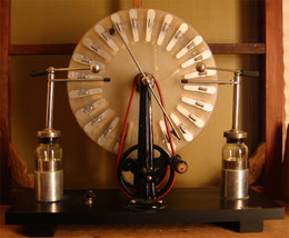
Wimshurst Machine
The Wimshurst machine is another device for generating high voltages with the advantage that it can create both positive and negative charges. It consists of two parallel insulating discs that are geared to rotate in opposite directions, neutralising rods and rods that collect the charge.
Although the discs are made of an insulating material, each disc has metal foil strips that are spaced radially on the outer surface of the discs. These plates help collect the excess charge that builds up on the insulating plates. The charge is removed by pairs of collecting combs. The Wimshurst machine works by induction, when the device is made there will be a small charge on the surface of the discs, which
An insulator is very difficult to discharge completely and there will always be regions on the discs which have small imbalances in charge. Consider such a small charge at the top of the disc, the charge induces an opposite charge on the second disc and the charges rotate away from each other, the foil sectors contain the charge. When the foil sectors pass under the neutralising rods they induce the opposite charge on the opposite side of the discs. This creates more charge on the foil sector. As the induced charges rotate around the disc the induced charges create a positive feed back of charge, so that on the top half of the front disc there is a build up of positive charge, while on the bottom half of the front disc there is a negative charge. On the back disc, the induction produces a negative charge on the top of the back disc and a positive charge on the bottom half of the back disc. Positive and negative charges are removed from the by combs which collect the charge and conduct it to metal spheres, until it become strong enough to jump across an air gap.
The discs make it difficult to visualise the build up of charge, so it might become clearer by considering the discs as opposite rotating cylinders. The inner cylinder represents the front disc and the outer cylinder the outer disc. On each cylinder the foil sectors are represented by the rectangular blocks that occupy the perimeter of the cylinders. The neutralising rod for the outer disc goes around the outer half of the outer cylinder. The second neutralising rod is placed at ninety degrees to the outer neutralising rod.
If one of the foil sectors on the outer cylinder has a slight charge on its surface, positive say. It will induce a negative charge on the foil sectors that is closest to it on the inner cylinder. As the cylinders rotate in oposite directions, the charges are separated. The energy for the electricity comes from the work done in turning the discs.
At A and B on the two discs, brushes at the ends of a neutralising rod connect diametrically opposite sectors momentarily. If we consider one disc, then the sector is oppposite, say, a negatively charged sector on the other disc. A (+) charge is induced on the inner side, while a (-) charge appears on the outer side, under the brush. At the diametrically opposite sector, the polarities are reversed, so the (+) charge appears on the outer side under the other brush. The charges on the outer sides are neutralized as a brief current flows, leaving the upper sector with a greater (+) charge, and the lower with a greater (-) charge. The induction of the charges does not depend on how much charge is already there, and equal signs of charge will not neutralize. The sectors charge to higher and higher potentials each time they pass beneath a brush, and their higher potentials serve to induce even greater charges.
Kelvin Electrostatic Generator
An electrostatic generator can be made by collecting charge from water droplets. To explain the operation of this device it is worthwhile considering the how charge can be collected using the more simple arrangement of a positively charged object brought close the tip dripping water tap as shown in Figure 3.
Overall water is electrically netural but there are a small fractions of the molecules, (the number comes from the pH of the liquid) which form ions and carry either a positive or negative charge. In the presence of a positively charged object, the negative ions in the water are attacted to the positive charge which the positive ions in the water are repelled. When a drop falls, the negative charge is isolated and the drop becomes negatively charged. The charge can be collected by catching the water in a metal container. The inside of the container becomes netural and the negative charge accumulates on the outside of the container.
All this is fine but it requires a charged object to attact the negative ions to the drop. The Kelvin electrostatic generator is illustrated in Figure 4. There are two dripping taps, two metal rings A and B which are connected to the buckets which collect the charge. A is connected to D and B is connected to C.
An initial imbalance in charge caused through the ions in the water causes the first initial drop to become very slightly positively or negatively charged. The small charge difference is enough to start the charging process. Let us say for the sake of argument, that the first drop falling into the bucket C is positively charged. The positive charge causes the ring B to become slightly positively charged which creates attracts negative ions from the water. This cause drops falling from the second tap to become negative. The negative charge stored in D also causes the metal ring A to become negatively charged which attracts positive ions from the dripping tap.
Thus the water is separated into two streams of positive and negatively charge drops and as water is collected in the buckets the charge on each of the buckets increases and reinforces the charge on the rings. The charge on the buckets builds up until it is great enough to cause a breakdown in the field across the spark gap at E or if the distance is too great between the spark gap, coronal discharge from sharp edges causes the charge to leak into the air.
I have built a Kelvin water dropper from Lego and various bits of junk.It has not been as easy to make work as you might expect.
Where does the energy come from to make the electricity? In order to raise water to the height of the nozzels work must be done and this takes the kinetic energy of the falling drops and slowing them down.
