In a case of an unpleasant event stay tuned and have enough power - use this UHF radio and large petrol power generator
Applications of Induction
AC Generator
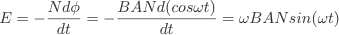
The ac generator uses Faraday's laws of induction, it consists of a coil of wire rotating a magnetic field. As the coil rotates it cuts the magnetic flux generating an EMF, the EMF produced is given by Faraday's law. The angle is changing at the angular frequency ω. Therefore at a given moment in time the angle between the normal to the area and the magnetic field lines will be ωt. Therefore the flux linkage, φN will be BAN cos(ωt). Differentiating cos(ωt) function with respect to time gives -ω sin(ωt). Therefore, the EMF is given by
The electrons flow first in one direction and then, in the other. The generator produces an alternating current. One advantage that AC has over DC is that it can easily be "stepped up" or "stepped down" with a transformer. In other words, a transformer can take a low-voltage current and make it a high-voltage current, and vice versa. Power is the product of voltage × current (P =VI). For a given amount of power, a low voltage requires a higher current and a higher voltage requires a lower current. Since metal conducting wires have a certain resistance, some power will be wasted as heat in the wires. This power loss is given by P = I2R. Thus, if the overall transmitted power is the same, and given the constraints of practical conductor sizes, low-voltage, high-current transmissions will suffer a much greater power loss than high-voltage, low-current ones. This holds whether DC or AC is used. However, it was very difficult to transform DC power to a high-voltage, low-current form efficiently, whereas with AC this can be done with a simple and efficient transformer.
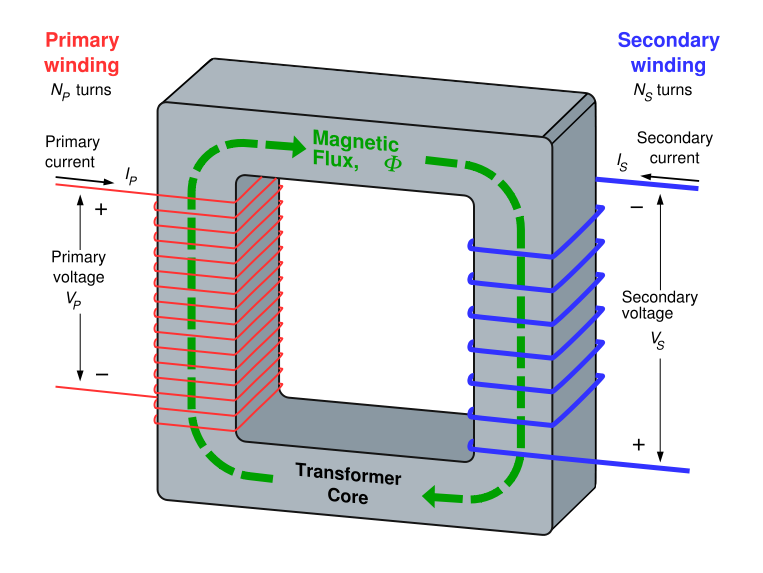
Transformers
Another application for electromagnetic induction is the transformer. Transformers are used to either increase or decrease the magnitude of an alternating current. The structure of a transformer consists of two coils, called the primary and the secondary, linked by an iron core which is used to concentrate the magnetic field. When an alternating current is applied to the primary, it generates a magnetic field in the iron core the changing magnetic field induces an EMF in secondary coil. Depending on the ratio of turns in the primary coil to the secondary determines whether the transformer is a step-up or step-down.