Capacitors
A capacitor is an electronic device for storing charge. Capacitors can be found in almost all but the most simple electronic circuits. There are many different types of capacitor but they all work in essentially the same way. A simplified view of a capacitor is a pair of metal plates separated by a gap in which there is an insulating material known as the dielectric. This simplified capacitor is also chosen as the electronic circuit symbol for a capacitor is a pair of parallel plates as shown in Figure 1.
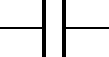
Figure 1. The symbol for an unpolarised capacitor.
Normally, electrons cannot enter a conductor unless there is a path for an equal amount of electrons to exit. However, extra electrons can be "squeezed" into a conductor without a path to exit if an electric field is allowed to develop in space relative to another conductor. The number of extra free electrons added to the conductor (or free electrons taken away) is directly proportional to the amount of field flux between the two conductors.
In this simplified capacitor the dielectric is air. When a voltage, V is applied to the terminals of the capacitor, electrons flow on to one of the plates and are taken off the other plate. The total number of electrons in the capacitor remains the same. There are just more on one the negative plate and fewer on the positive plate.
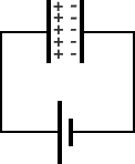
Figure 2. Charging a capacitor with a battery
If the volage were increased the increased potential difference between the plates would push more electrons on to the negatively charged plate. We could measure the charge stored on the plate as a function of different applied voltages.
At zero voltage, the capacitor plates are neutral and so no charge is stored. (we assume that we started with a fully discharged capacitor), at a voltage V the charge on the plates is Q and at twice the voltage, the charge is doubled. We find that for increasing voltage the charge increases linearly. We can plot this as a straight line.
Suppose that we go away and do some research and come back with a better capacitor which stores more charge for a given voltage we can plot the result of the charge stored as a function of applied voltage
This would be represented as another line with a steeper slope. If we plotted lots of graphs for different capacitors we would get many straight lines. We can say that a measure of the capacitance is the how much the charge is stored for a given voltage. This is sometimes expressed as Q=CV.
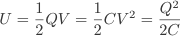
Of course in charging the capacitor work must be done to move the charge. Therefore energy must be supplied and this energy is available when the capacitor is discharged.
The work done is given by W=qV. Initially the charge is easily moved onto the plates of the capacitor, however as more charge is moved onto the capacitor plates the repulsive force between the charges makes it harder to add charge, when the repulsive force of the charges equals the power of the battery, no more charge can be moved onto the plates. Therefore the average work is 1/2qV. If we look at our graph of charge against voltage we can recognise this is the same as the area under the curve. In general, the work done is equal to the energy transferred. Mathematically,

Factors Affecting Capacitance
How can we increase the capacitance of a parallel plate capacitor? There are three factors which affect the capacitance of a parallel plate capacitor.
Area
By increasing the area of the plates we can put more charge on the plates before the repulsive forces becomes a problem. Therefore, the capacitance is proportional to the overlapping surface area of the plates. In a variable capacitor the overlapping area can be increased or decreased by rotating interpenetrating plates thus increasing or decreasing the capacitance. Electrolytic capacitors have their plates etched to produce a rough surface which increases the surface area still further.
Separation
Decreasing the separation of the plates, decreases the voltage of the capacitor since the electric-field is not affected by the distance between the plates. The voltage on the capacitor is V=Ed. Therefore the voltage increases. For a constant charge, Q, C=Q/V =Q/Ed.
Dielectric Constant
The capacitance of a parallel plate capacitor is given by C=εr A/d, where A is the area of the plates, d is the separation between the plates and εr is the relative permiliability of the dielectric between the plates. The relative permiability is some factor, K multiplying the permiability of free-space ε0. ε0 has a value of 8.85x10⁻¹² F.m-1.
A full list of relative permiabilities can be found for almost any dielectric material. The greater the relative permiability the greater the capacitance of the capacitor. Some good materials are Mica, polystyrene, oil.
εr=K ε0
Capacitor Networks
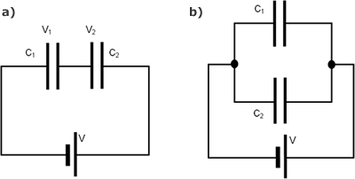
Figure 3. Capacitor networks in Series and Parallel
Series
Consider the series network of capacitors shown in Figure 3a. where the positve plate is conected to the negative plate of the next.What is the equivalent capacitance of the network? Look at the plates in the middle, these plates are physically disconected from the circuit so the total charge on them must remain constant. It follows that when a voltage is applied across both of the capacitors, the charge +Q on the positive plate of capacitor C1 must be balanced by the charge -Q on the negative plate of capacitor C2. The net result is that both capacitors possess the same charge Q. The potential drops V1 and V2 across the two capacitors are in general, different. However, the sum of these drops equals the total potential drop V applied across the input and output wires. V=V1 + V2. The equivalent capacitance of the pair is again CT=Q/V. Thus, 1/CT = V/Q = (V1 + V2)/Q = V1/Q + V2/Q giving
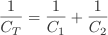
In general, for N capacitors connected in series, is

By connecting capacitors in seires you store less charge so does ever make sense to connect capacitors in series? It is sometimes done because capacitors have maximum working voltages, and with two 900 volt maximum capacitors in series, you can increase the working voltage to 1800 volts.
Parallel
For a parallel circuit such as in Figure 3b. the voltages are the same across each component. However the total charge is divided between the two capacitors since it must distribute itself such that the voltage across the two is the same. Also, since the capacitors may have different capacitances C1 and C2 the charges Q1 and Q2 must also be different. The equivalent capacitance CT of the pair of capacitors is simply the ratio Q/V where Q=Q1+Q2 is the total stored charge. It follows that CT = Q/V = (Q1+Q2)/V = Q1/V + Q2/V giving

It is fairly obvious from the previous discussion that for N capacitors in parallel, the total capacitance is

The overall capacitance increases by added together capacitors in parallel so we create larger capacitances than is possible using a single capacitor. High-energy physics labs often have large banks of capacitors which can store large quantities of energy to be released in a very short time. The largest bank of capacitors in 2006, can store 50 MJ of energy.
Charging and Discharging Capacitors
A circuit consisting of a battery, a switch, a resistor and a capacitor in a series loop is called an "RC" circuit. Kirchoff's voltage law for this circuit is
V = IR + Q /C. When expressed purely in terms of the charge, this becomes
V = dQ/dt R + Q/C.
This is a differential equation, whose solution is an exponential function. When the switch is closed, the capacitor charges over time:
Q = Qf (1 - e-t/RC),
where Q is the charge at time t and Qf is the final charge on the capacitor. Note that Q never equals Qf , but as t gets extremely large, Q gets arbitrarily close to Qf. The product RC is called the RC time constant, and is a characteristic quantity of the RC circuit. When t = RC, the capacitor has charged to a fraction (1 - 1 / e, about 63%) of its final value. It is necessary to use a time constant, and not some sort of terminal time, since the process is asymptotic. Its value is an arbitrary choice; we naturally choose a value in terms of the exponential base (when the exponent is negative one).
Flash Animation 1. Change the values of the resistor and capacitor to see the effect on the time for the capacitor to reach peak voltage
Flash Animation 2. Charge the capacitor until it reaches its peak and then discharge it. How does the values of R and C affect the processes?
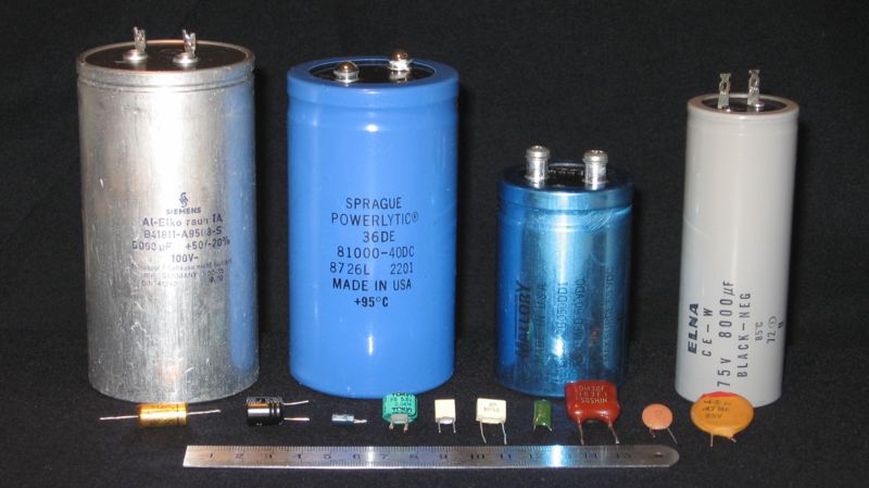
Types of Capacitor
Electrolytic Capacitors
Aluminum electrolytic capacitors are made by layering the electrolytic paper between the anode and cathode foils, and then coiling the result. The process of preparing an electrode facing the etched anode foil surface is extremely difficult. Therefore, the opposing electrode is created by filling the structure with an electrolyte. Due to this process, the electrolyte essentially functions as the cathode.
Electrolytic capacitors are soaked in a liquid or paper impregnated with a liquid which is not a dielectric but when a voltage is applied creates a layer of aluminium oxide which acts a the dielectric. The reaction is dependent on the polarity of the applied voltage. If the polarity is reversed the capacitor will produce a gas and is likely to explode or burst because of the pressure inside and so are not suitable for altenating current applications.
MEMs Capacitors
Micro Electro-Mechanical Systems (MEMs) are small devices manufactured from Silicon. Plate capacitors can be fabricated which show small changes in capacitance a the separation of the plates is increased or decreased. The small devices can be used as sensors and gyroscopes.
Common types of devices are the parallel plate capacitors for position sensing. Also, interpenetrating comb-like structures, in which the capacitance may be altered using by moving one comb relative to another, either in the transverse direction or longitudinal direction. Because of their small size, the variation in capacitance is very small, of the order 10-15 F. (femto-Farads).
Tantalum Capacitors
Tantalum capacitors are polarised and have low voltage ratings like electrolytic capacitors. They are expensive but very small so they are used where a large capacitance is needed in a small size such as mobile phones or laptop computers. These capacitors have increasingly become an important as the demand for ever smaller electronic gadgets has grown. Columbite-tantalite - coltan, for short, the ore from which tantalum is refined is mined in Australia, Egpyt. The high demand for the ore has also financed civil wars in the Democratic Republic of the Congo. A UN security council report charged that a great deal of the ore is mined illegally and smuggled over the country's eastern borders by militas from neighbouring Uganda, Burundi and Rwanda providing the revenue to finance the military occupation of the Congo.
Supercapacitors
Supercapacitors are capacitors which have the ability to store large amounts of charge, and therefore energy, in a very small volume. Energy storage is by means of static charge rather than of an electro-chemical process that is inherent to the battery. Applying a voltage differential on the positive and negative plates charges the supercapacitor. This concept is similar to an electrical charge that builds up when walking on a carpet. The supercapacitor was first conceived in 1957 but now research is focused on using these as a light weight power sources as an alternative for batteries. the supercapacitor crosses into battery technology by using special electrodes and some electrolyte. Supercapacitors could find applications such as temporary back-up power supplies in the electrical power grid or providing the initial burst of energy to get electric cars moving.
Summary
Capacitors have the ability to charge and release their stored charge very quickly allowing them to function in many ways. They have important places in everything from voltage stabilizing circuits in sensitive electronics to helping convert AC power to DC to charge batteries in everything from mobility scooters to your laptop computer.
Capacitors are devices which store charge. The capacitance is defined as the ratio of charge store per unit voltage. C=Q/V
The capacitance of a parallel plate capacitor is given by C=εrA/d.
The energy stored in a capacitor is calculated by the work done in moving charge onto the plates. dW = V dq. The energy store is the area under the charge/voltage plot. 1/2QV or from C=Q/V, 1/2CV2 = 2Q2/C.
